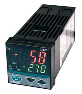
1/16 DIN Ramp/Soak Temperature/Process Controllers |
| CN6201 Series |
|
 |
|
|
1/16 DIN Ramp/Soak Temperature/Process Controllers
 |
| Click for larger image. |
|
|
|
|
|
|
 |
CN6201 Series are in the end of life cycle. As a possible substitute & upgrade, please check out Newest Released 16 DIN Dual Display PID Controller CND3 Series for more advanced features with better price.
The CN6201 Series temperature
controllers have 1 program pattern
consisting of 16 segments that can
easily be set and operated. The
2 event outputs are provided as
standard. External contact input,
RS485 communication and
retransmission outputs are optional.
The universal input supports
thermocouple, RTD and voltage input
types and the 3 types of outputs. The
front panel has a splash-proof and
dust-proof design (IP65).
| Input Type |
Range (°C) |
Range (°F) |
| Thermocouple |
K |
-270 to 1370 |
-300 to 2500 |
| 0 to 600 |
32 to 999.9 |
| 0 to 400 |
32 to 750 |
| -199.9 to 200 |
-300 to 400 |
| J |
-199.9 to 999.9 |
-300 to 2100 |
| T |
-199.9 to 400 |
-300 to 750 |
| E |
-199.9 to 999.9 |
-300 to 1800 |
| R |
0 to 1700 |
32 to 3100 |
| S |
0 to 1700 |
32 to 3100 |
| B |
0 to 1800 |
32 to 3200 |
| N |
-200 to 1300 |
-300 to 2400 |
| L |
-199.9 to 900 |
-300 to 1600 |
| U |
-199.9 to 400 |
-300 to 750 |
| Platinel 2 |
0 to 1390 |
32 to 2500 |
| RTD |
Pt100 |
-199.9 to 850 |
-199.9 to 999.9 |
| 0 to 400 |
32 to 750 |
| -199.9 to 200 |
-300 to 400 |
| -19.9 to 99.9 |
-199.9 to 999.9 |
| JPt100 |
-199.9 to 500 |
– |
SPECIFICATIONS
PV/SP Data Display: 4-digit, PV/SP separately
PV Inputs:
Method: Universal input
Thermocouple: Types K, J, T, E, R, S, B, N, L, U, Platinel 2
RTD: Pt100, JPt100
Voltage: 0 to 100mV, 0 to 5V, 1 to 5V, 0 to 10V
Input Accuracy:
Thermocouple: ±2°C ±1digit
RTD: ±1°C ±1digit
Voltage (mV, V): ±0.3% ±1digit
Sampling Period: 500 ms
Number of Program Patterns: 1
Number of Program Segments: 16
Program Time Span: 0 s to 1,599 hr
Accuracy of Program Time Span: ±2% of program time span
Event Output:
Number of Points: 2 relay
Type: PV and time
Power Supply: 100 to 240 Vac or 24 Vac/dc (optional)
Safety and EMC Standard: CSA and UL
Construction (Front Protection): IP65
Dimensions: 48 W x 48 H x 100 mm D (1.89 x 1.89 x 3.94")
Weight: Approx. 200 g (0.44 lb)
External Contact Input (Optional): Run/reset, hold/cancel hold
PV Retransmission Output: 4 to 20 mAdc
RS485 Communication (Optional): MODBUS/Ladder/PC-link protocol
24 V Power Supply (Optional): 24 Vdc/24 Vac
Measured Value (PV) Input
Input: 1 point
Type: Universal, Selectable by Software
Accuracy (at 23 ±2°C Ambient Temperature):
Thermocouple: ±2°C ±1digit
Input -200 to -100°C: ±4°C
Input -100 to -0°C: ±3°C
Types R and S: ±5°C (±9°C for 0 to 500°C)
Type B: ±9°C (accuracy is not guaranteed for 0 to 400°C)
RTD: ±1°C ±1digit
Voltage(mV, V): ±0.3% ±1digit
Sampling Period for Measured Value Input: 500 ms
Burn-Out Detection: Functions for thermocouple or RTD input (burn-out upscale only; cannot be switched off)
Input Resistance: 1 MΩ or greater for thermocouple or mVdc inputs; approx. 1 MΩ for Vdc input
Maximum Allowable Signal Source Resistance: 250 Ω for thermocouple or mVdc inputs; 2 kΩ for Vdc input
Maximum Allowable Wiring Resistance for RTD Input: 10Ω/wire (the resistance values of 3 wires must be the same.)
Allowable Input Voltage: ±10 Vdc for thermocouple or mVdc inputs; ±20 Vdc for Vdc input
Noise Rejection Ratio:
Normal Mode Noise: Minimum 40 dB (50/60 Hz)
Common Mode Noise: Minimum 120dB (90 dB for Vdc input)
Error of Reference Junction Compensation: ±1.5°C (at 15 to 35°C); ±2.0°C (at 0 to 50°C) The reference junction compensation cannot be switched off
Applicable Standards: Thermocouple and RTD, JIS/IEC/DIN, (ITS90)
Retransmission Output (Optional)
Output Signal: Measured value in 4 to 20mAdc can be scaled.
Maximum Load Resistance: 600 Ω
Output Accuracy: ±0.3% of span (at 23 ±2°C ambient temperature)
Power Supply and Isolation
Power Supply:
Voltage:
Frequency: 50 or 60 Hz
Maximum Power Consumption:
Memory: Non-volatile
Withstanding Voltage: Between Primary and Secondary
Terminals: 1500 Vac for 1 minute (see Notes 1, 2 and 3)
Insulation Resistance: Between Primary and Secondary
Terminals: 20 MΩ or more at 500 Vdc (see Notes 1, 2 and 3)
Note 1: The primary terminals are the power
supply terminals and event output terminals.
The secondary terminals are the analog input
and output terminals, the voltage pulse output
terminals, and the contact input terminals.
Note 2: The withstanding voltage is specified
as 2300 Vac per minute to provide a margin
of safety.
Note 3: AC/DC 24 V terminals are secondary
terminals.
|
|
|
 |
|
 |
† Price are shown in RMB.
Note: Comes with complete operator’s manual.
|
|
 |
|
 |
|  |
|
Related Links -
Related Products
|
|
|
|
|
|
|
|
