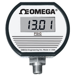
Digital Pressure Gauges with Alarms and Analog Output Functions |
| DPG1000 Series |
|
 |
|
|
|
|
|
¥
5,900.00
DPG1000ADA-15G-1N
|
| • |
AC or DC Powered with Dual Alarms
|
| • |
DC Powered with Dual Alarms and Analog Output
|
| • |
Ranges between 15 psi and 3000 psi
|
| • |
Normal or Reverse Acting Alarms
|
| • |
Hi/Lo, Hi/Hi, or Lo/Lo Alarms available
|
| • |
Colored LED Alarm Status Indicators
|
View related products - Pressure Gauges
|
| |
|
|
|
 |
Using the DPG1000ADA and
DPG1000DAR Alarm Outputs
Normal (Fail-safe) vs. Reverse
Action—The convention for alarm
action is that with the normal or
fail-safe configuration, the alarm
output relays will be CLOSED (relay
energized) for a clear or non-alarm
condition and OPEN (relay not
energized) for an alarm condition.
This is primarily for users who
require an alarm condition if
the gauge loses power or suffers a
catastrophic failure. In the wiring
diagrams, the normally closed and
normally open designations refer to
standard relay terminology (i.e., the
relay contact status with the relay
coil not energized).
Therefore, with the normal
(fail-safe) configuration in a green
or non-alarm condition, the relay
will be energized so that continuity
can be expected between the
common and normally open leads.
In a red or alarm condition, the relay
will be open (not energized) so
that continuity can be expected
between the common and normally
closed leads.
Contact Rating and Protection
The contacts of the alarm relays
are rated at 1 A/24 Vdc or 0.5 A/
115 Vac. Switching loads greater
than the rating, or switching large
inductive loads, will shorten the
useful life of the contacts. In lowlevel
switching or with dry contacts,
the user should consider whether
external contact protection, such
as snubber networks or arc
suppression networks, is required
to protect the contacts.
In addition, no internal fusing is
included in the DPG1000 contact
circuits. The circuit external to the
gauge alarm outputs should be
fused by the user in applications
in which good design dictates
this practice.
Using the DPG1000DAR
Analog Output
The analog output is easy to use
if a few system considerations are
observed. The DPG1000DAR is DC
powered, with the gauge power
supply (–) tied to the 4 to 20 mA (–).
Therefore, the DC supply (–) lead
should be considered common with
regard to the analog output
(–) or ground connection in the
user’s system.
Be sure to observe the output
compliance (voltage drive)
capabilities of the gauge. The
compliance, and therefore the
maximum loop resistance the output
can drive, is a function of the supply
voltage to the gauge. Consult the
manual for maximum loop
resistance vs. supply voltage. Too
large a loop resistance will cause
the gauge output to “limit”
or saturate before reaching its full
20 mA output.
DPG1000ADA AC/DC Powered with Dual Alarms
SPECIFICATIONS
Accuracy: ±0.25% FSO or better, ±1 least-significant digit (includes linearity, hysteresis, repeatability)
Controls and Location: Display zero/span, non-interactive, ±15% range; setpoint 1 and setpoint 2, 0 to 100% range; top-accessible, multiturn potentiometers
Alarm Deadbands (Hysteresis): 1% of FSO, standard
Alarm Outputs: Dual form “C” (SPDT) relay contacts; individual setpoint 1 and setpoint 2 settings via top-accessible multiturn potentiometers; high/low alarm configuration standard, others available; relay contacts rated 1 A/24 Vdc, 0.5 A/115 Vac, non-inductive
Alarm Indicators: Bicolor (red/green) LEDs on front panel
Test Function: Front-panel TEST button, when depressed, toggles both SP1 and SP2 alarm status, independent of pressure input, to allow testing of system operation
Alarm Response Time: 100 ms typical
Power: Any AC source of 8 to 24 Vac, 50/60 Hz, or any DC source of 9 to 32 Vdc, 1.0 W maximum; optional wall-mount power supply available to operate on 115 Vac (DPG1000-PS)
DPG1000DAR DC Powered with Dual Alarms and 4 to 20 mA Output
SPECIFICATIONS
Accuracy: ±0.25% FSO or better, ±1 least-significant digit (includes linearity, hysteresis, repeatability)
Controls and Location: Display zero/span, non-interactive, ±15% range; setpoint 1 and setpoint 2, 0 to 100% range; test calibration level, 0 to 100% range; top-accessible, multiturn potentiometers analog output zero/span; internal potentiometers
Alarm Deadbands (Hysteresis): 1% of FSO, standard
Alarm Outputs: Dual form “C” (SPDT) relay contacts; individual setpoint 1 and setpoint 2 settings via top-accessible multiturn potentiometers; high/low alarm configuration standard; relay contacts rated 1 A/24 Vdc, 0.5 A/115 Vac, non-inductive
Alarm Indicators: Bi-color (red/green) LEDs on front panel
Alarm Response Time: 100 ms typical
Analog Output: 4 to 20 mA DC; output drive (compliance) determined by power source
Analog Output Response Time: 50 ms, typical
Test Function: Front-panel TEST button, when depressed, toggles both SP1 and SP2 alarm status and simultaneously sets display and analog output to “calibration” level, independent of pressure input, to allow testing system operation
Power: Any DC source of 9 to 32 Vdc, 1.0 W max
Electrical Connection: 0.9 m (3') long, 4-conductor 22 AWG shielded cable for power and retransmitted output; 0.9 m (3') long, 6-conductor 22 AWG cable for alarm contacts
ALARMS (final siffix 1N standard)
1 = HI/LO (standard)
2= HI/HI
3= LO/LO
N = Normal Acting (standard)
R = Reverse Acting
Example: DPG1000ANA-15G-3R HAS LO/LO ALARMS, Reverse Acting
For alternative Digital Pressure Gauges please visit the following links:
DPG-108
DPG104-DPG104S
DPG-110
DPG-101
|
|
|
|
|
|
† Price are shown in RMB.
Note: Comes complete with operator’s manual. Note: To order another alarm configuration, replace “-1N” with alarm configuration from table above.
Ordering Example: (1) DPG1000ADA-15G-1N AC/DC powered, 15 psig range, two alarms, one Hi, one Lo, ¥5,900.00
|
|
|
|
|
| |
|
Related Links -
Related Products
|
|
|
|
Related Products
|
 |
DPG5600 Series:
|
|
Min/Max Digital Pressure Gauges with Display Backlighting
|
|
|
|
|
|
 |
DPG5500 Series:
|
Min/Max Digital Pressure Gauges
With Selectable Pressure Units
|
|
|
|
|
|
|
|
|
|
|